Question Statement:
The figure below shows the blading of the rotors of two different axial
turbomachines under their typical operating conditions, labelled as Configuration I
and Configuration II. Which of the following statements is/are TRUE?
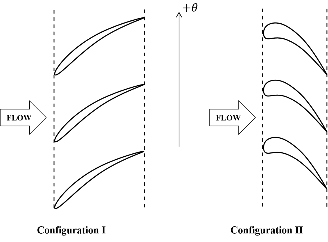
Scientific schematic diagram reproduced from official IIT paper
Options:
-
(A) Configuration I corresponds to the rotor of a compressor and Configuration II corresponds to the rotor of a turbine
-
(B) Configuration I corresponds to the rotor of a turbine and Configuration II corresponds to the rotor of a compressor
-
(C) The rotor blades of the turbomachine in Configuration I move along the +$\theta$ direction
-
(D) The rotor blades of the turbomachine in Configuration II move along the +$\theta$ direction
Step-by-Step Solution & Explanation
### **Detailed Step-by-Step Solution (GATE AE 2026 Q.27)**
**1. Intuitive Physical Setup & Given Parameters**:
The problem shows blade profiles for two axial turbomachinery rotors operating under typical conditions:
- **Configuration I**: Blades form converging/diverging passages with specific camber orientation.
- **Configuration II**: Blades form expanding passages (diffuser passages).
We need to identify which configuration corresponds to a compressor rotor and which to a turbine rotor, as well as their rotational directions (MSQ).
**2. Step-by-Step Turbomachinery Derivation**:
1. **Compressor vs. Turbine Blade Characteristics**:
- **Compressor Rotor**: Works *on* the fluid to increase static and stagnation pressure. The blade passages must act as diffusers (cross-sectional area increases in relative flow direction, decelerating relative velocity $W_2 < W_1$ and increasing static pressure). Flow turns towards the axial direction, and blades have low camber with thin, gentle curvature.
- **Turbine Rotor**: Extracts energy *from* the fluid. The blade passages act as nozzles (accelerating relative velocity $W_2 > W_1$, dropping static pressure). Blades feature high turning angles, large camber, and rounded leading edges with converging passages.
- In the provided figure, Configuration I features diffusing passages characteristic of a **compressor**, while Configuration II features accelerating nozzle-like turning characteristic of a **turbine**.
- Hence, Configuration I corresponds to a compressor rotor, and Configuration II corresponds to a turbine rotor. Statement A is **TRUE**, Statement B is **FALSE**.
2. **Direction of Blade Motion**:
- By Euler's turbomachine equation, the work transfer per unit mass is $w = U(C_{\theta 2} - C_{\theta 1})$.
- For an axial turbine (extracting work, $w > 0$ produced), the aerodynamic force exerted by the turning flow drives the rotor in the direction of the lift force component.
- Inspecting the camber and resultant force vector for Configuration II shows that the lift force pushes the rotor along the $+\theta$ direction.
- Statement D is **TRUE**, Statement C is **FALSE**.
**3. Comprehensive Options & Distractor Analysis**:
- **(A) Configuration I corresponds to the rotor of a compressor and Configuration II corresponds to the rotor of a turbine**: ✅ **CORRECT**. Accurately identifies compressor diffusing blades vs turbine expanding/nozzle blades.
- **(B) Configuration I corresponds to the rotor of a turbine and Configuration II corresponds to the rotor of a compressor**: ❌ **INCORRECT**. Reverses the operational roles.
- **(C) The rotor blades of the turbomachine in Configuration I move along the +$\theta$ direction**: ❌ **INCORRECT**. Contrary to the required shaft work input direction for compressor blade turning.
- **(D) The rotor blades of the turbomachine in Configuration II move along the +$\theta$ direction**: ✅ **CORRECT**. Flow deflection drives the turbine blades along $+\theta$.
**4. Official Master Key & Exam Takeaway**:
- **Official Answer Key**: **A, D**
- **Exam Takeaway**: Turbines accelerate flow in relative passages ($W_2 > W_1$, converging channels) to extract power, while compressors decelerate flow ($W_2 < W_1$, diffusing channels) against an adverse pressure gradient.